Introduction
EPISODE GUIDE
EPISODE 1
EPISODE 2
- MY LAST SUMMER AT THE FELLOWSHIP AND THE LOS ANGELES 60 YEARS OF LIVING ARCHITECTURE PAVILION
- THE ROSS COTTAGE AND A THESIS
- IN WRIGHT'S HAND
EPISODE 3
- MR. WRIGHT'S PEOPLE OR MRS. WRIGHT'S PEOPLE
- THE ZIMMERMAN HOUSE
- DESERT MASONRY
OTHER ESSAYS
- WHAT KIND OF A MAN WAS MR. WRIGHT TO WORK FOR?
- THE MERRY WIVES OF TALIESIN, A FEW HUSBANDS, PLUS SOME MERRY MEN
- A SUMMER'S WORK -- NOT IN THE TALIESIN DRAFTING ROOM: THE NEILS HOUSE
"IN THE CAUSE OF ARCHITECTURE":
COMMENTARIES IN MEMORIAM
Frank Lloyd Wright geometry
3
the zimmerman house
The year was 1951 and Frank Lloyd Wright was 84 years old but very much alive, creatively, spiritually and intellectually. Time had been kind to Wright’s creative powers. The spark was still there when he chose to apply himself. At 84 and having accomplished several lifetimes of creative work in a span of 62 years, the urge to prove himself was not always paramount in his routine work. It took a special circumstance to light the fire of a truly creative architecture. The most creative years of his career were obviously the mid- to late 1930’s. This was the era of Fallingwater, Jacobs #1, the Johnson Administration Building, Taliesin West, and many very good residential jobs. Wright would never surpass that burst of creative energy again, but that doesn’t mean there was not good work being accomplished in the later years.
The post war years brought forth many superior works, among which are the Morris Shop, the Jacobs hemicycle, and the Rogers Lacy and Huntington Hartford projects. The client was always critical for Wright in the creation of a masterwork. It is hard to imagine the Coonley house without Mrs. Coonley and her choice of Wright because “his work bears the countenance of principal.” Herbert Johnsons and Edgar Kaufmann were hardheaded businessmen, but once they took the bait and they realized what was at stake, they stayed the course. The same general rule applied to the average client. When a client took Wright at his word
|
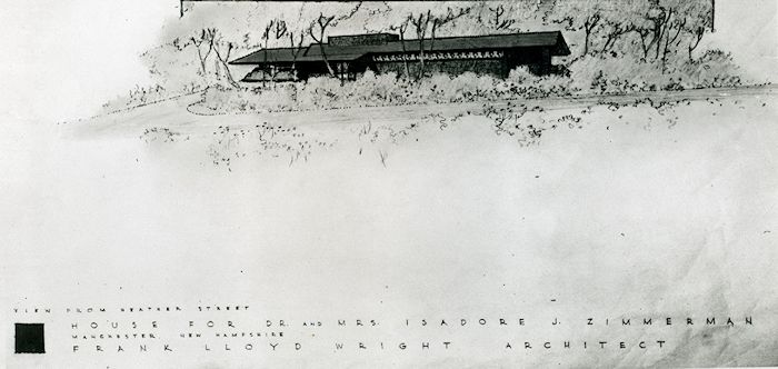
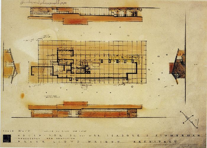
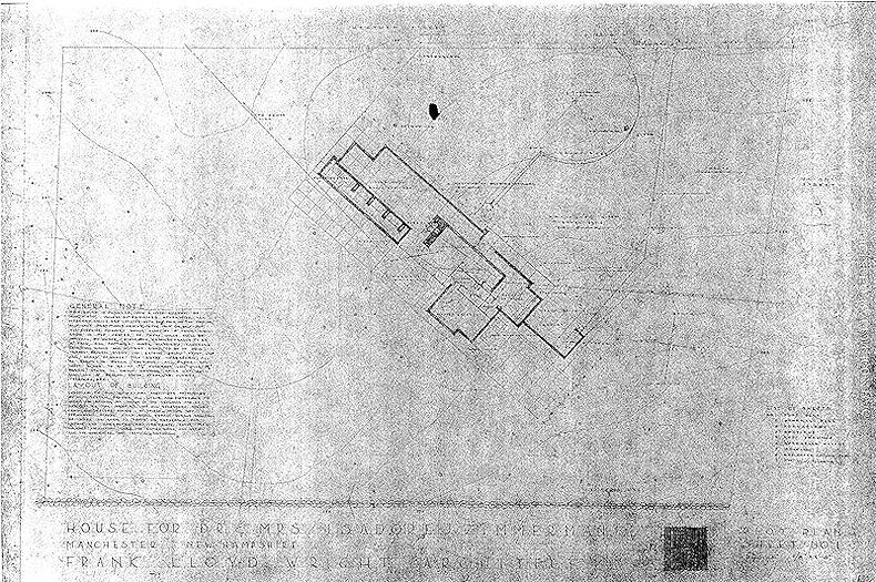
that he was there to serve them, and when they pressed their needs within the bounds of ‘good taste.’ Wright responded in kind. However, if Wright took a dislike to a client for whatever reason, real or perceived, there was remote chance for a good house. The post war years were also the beginning of financial stability for Wright for the first time in his life. The work came pouring in and the attention Wright gave to the individual job was a function of the nature of the job and the nature of the client. With the Carlson house it was the client who had been kind to Wright in his Arizona Highways publication and who Wright liked. The Lovness couple challenged Wright, he liked them and they ended up with two very good cottages. With Maginel Barney and David Wright it was family. But there were many good run of the mill houses during this period. The Zimmerman house falls within this category of good houses. PURPOSE It is still 1951 and Mr. Wright has just told me that he was going to send me to New Hampshire to supervise the construction of the Zimmerman House. I don’t remember my reaction but I did pull the drawings to take a look. I didn’t like everything I saw. Design development considerations were clearly in order. My purpose in writing about the Zimmerman house is to give a first hand account of how one of Wright’s houses came into being, from the first contact to the client’s move in. My personal account starts when Mr. Wright told me he was sending me to New Hampshire to supervise the Zimmerman house. My account is probably not typical of how a Wright house was built, if there is any such thing as typical for a Wright house, but this is my own very personal recollection of that process. After Mr. Wright told me he was going to send me to supervise the construction of the Zimmerman house, the first thing I did was to pull the drawings and have a look. The house needed work. I took the position that, if I had been the apprentice that had done the working drawings in the first instance, that I would have interpreted the preliminary drawings in terms of my own understanding of Wright’s work. It was what was expected of an apprentice in the process of doing the working drawings. There were probably times when Wright was involved in every decision concerning a house, but these were not those times. This house wasn’t Jacobs #1, and Mr. Wright was involved in other, major projects at this time. There are also indications going back to the Oak Park Studio that Wright made a habit of turning a job over to a draftsman and let him carry the ball. Subsequently, if Mr. Wright didn’t like what he saw; it was always blamed on the draftsman, not Wright’s inattention. At any rate, in this instance, I simply took it upon myself to make whatever changes I considered appropriate to make, and that I didn’t think required Mr. Wright’s involvement. Later on I sent drawings for all the cabinet work for his approval. I remember that clearly because it took weeks, and a couple of letters, to get that approval. Jack would wait for an opportune time to show Mr. Wright drawings submitted for his approval. It was all a question of timing. I probably went though this process more for the benefit of the Zimmermans than getting Mr. Wright’s approval. I knew that Jack would present the drawing for Mt. Wright’s signature and he would sign them without ever taking a serious look at what he was signing. But before we go there, let’s take a look at how the Zimmermans decided on Wright as their architect.<.p> Dr. Isadore Zimmerman was a urologist and his wife Lucile was his nurse, and he was in private practice in Manchester, New Hampshire. Their search for an architect turned to their local library after eliminating the local cadre of architects. There they found Frank Lloyd Wright’s Modern Architecture, Being the Kahn Lectures and An Autobiography. The ethical dialectic was important to both of them and that consideration was probably at the root of their initial interest in Wright. These books were not picture books but philosophical tracts. Wright’s presentation of his architectural philosophy in An Autobiography can’t be separated from the ethics of Emerson, Whitman, Thoreau and Veblen. Although Wright couched his argument in ethical terms his goal was simply to create beautiful buildings. Ethical considerations were the beginning of that quest and a necessary ingredient in the final work of art, but the artist, practicing his craft, was the essential ingredient that turned ethical considerations into a work of art. The site was a three-quarter acre lot in a sparsely populated part of the city that had never been “improved.” The property was in a very primal state with 10 to 15 mature 10” to 20” maple pine oak and birch trees and probably 50 saplings that over a period of years grew into real trees and turned the site into a New England version of Evangeline’s “Forest Primeval’. There were rhododendrons at the east end of the lot at Union Street that were to remain as native habitat. But there will be more about site improvements later. The Zimmerman’s first letter to Wright to Wright was written on June 27, 1949, and simply asked if he would consider designing a modest house for them. Wright responded in the affirmative and a visit with Wright at Taliesin was set for August 10, 1949. A visit with Wright at Taliesin is a pretty formidable experience even for the initiated, but for a new client, who is not a Kaufmann or a Johnson, it must be an experience to be remembered. They brought a topographic site plan with them and discussed their requirements with Wright. They followed up the visit with a gracious thank you letter and a detailed list of requirements along with a jug of New England maple syrup. The letter said in part that, “…I expect that our proposed house will have positive educational role to play in our community...” And that it did.. It is now a house museum of the Currier Gallery of Art and is open to visitors on a regular basis. There was a follow-up letter to Wright two weeks after the initial meeting adding functional requirements, but given with the caveat for them not to interfere with “ your architectural creation…” and that you should have a “…free hand limited only by our financial status…” “…conditioned by reason…” Good luck. PRELIMINARY DRAWINGS Wright advised the Zimmermans that their preliminary drawings would be in the mail on October 12, 1950, one year and two months after their initial visit. The length of time involved implies that that job waited for Wright to sit at his drafting board and make a decision about the design of the house. The arrangement of the house on the site bears Wright’s sensitivity to the landscape. The house was a rectangle on a rectangular lot, but Wright rotated the house at an angle to the street around a naturally occurring granite outcropping. This scheme provided a large entrance court at the street side and a large yard at the garden side of the house. This was an unconventional thing to do in a very conventional neighborhood…but on the conventional side this was a house with brick masonry walls with a cast-stone wall cap. It was reminiscent of the traditional New England masonry building with cut limestone windowsills and lintels; a very vernacular solution to a vernacular problem. On the other hand on the street side of the Zimmerman house there was a row of perforated cast stone blocks topping off the masonry wall that was very un-vernacular for New England. But it worked.
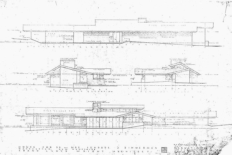
Conceptually the Zimmerman house was a very strong design. There were two gable roofs, the major roof, unequally pitched, with the lesser pitch facing the garden and a minor roof, equally pitched, facing the street. An eyebrow of the minor roof leading to the entrance engaged the major roof and joined the two. A raised masonry core similar in concept to Jacobs#1 defined the utility core and provided the anchor to the site. The house was open to the garden side and closed to the street side with a masonry wall topped by a row of perforated cast stone blocks. The Zimmerman’s wisely and enthuastically embraced the concept while holding reservations about elements of the plan. They met and corresponded with Wright over the next few months and changes were instituted. The perspective showed a handsome house that had the look of an original and the Zimmermans were delighted with that aspect. There were some problems with the floor plan but the Zimmermans took that in stride because those problems could be solved. The overall exterior appearance was excellent and the living room was a handsome gracious space. All the other plan problems could be worked out. In the year of 1950 Mr. Wright was not as engaged as he might have been with the routine job. Drafting room supervisor Jack Howe apparently waited a year and two months for Wright to make the initial decisions on this job. The layout of the house on the site is obviously Wright’s doing, although there are no drawings to substantiate that claim. However, I can see Wright laying out the house on an angle to the street and showing the house as one long rectangle. The original floor plan and perspective bore the skeleton of the Dabney house (Note 1). The preliminary drawings, as presented to the Zimmermans, were very poorly developed, and should never have been sent to a client in that stage of evolution. Wright frequently pulled something out of the files to be used on a current job. He had been doing this for his entire career. Not exactly the most creative approach but this was Frank Lloyd Wright’s way, and with proper design development, it worked. In the Oak Park Studio where this practice developed the ‘design developers’ were experienced draftsmen, often licensed architects. In the Fellowship drafting room they were mostly untrained, but reasonably intelligent and enthusiastic, apprentices of varying capability. For the client, it was the luck of the draw.
Two weeks after receiving the preliminary drawings the Zimmermans met with Mr. Wright at the Plaza Hotel in New York requesting additional changes. Through persistence and gentle persuasion, they made their needs known and probably achieved their goal. There was another letter on January 25, 1951, praising the house but requesting additional changes. These letters would be considered to be bothersome by Wright. He didn’t care about how much closet space there was or where the dishwasher was, so they were passed on the apprentice working on the job to be dealt with. By the time the working drawings blueprints arrived on April 7, 1951, approximately 5 months after the after the preliminary drawings, most of the problems had been solved, at least superficially. The master bedroom had been expanded to form its own wing and other problems had been dealt with in a reasonable manner. But before we go any further, let’s take a look at the generic Wright unit system. The unit system came into full maturity very early in the game with the Ross and Gerts cottages of 1902. They were both all wood structures with walls centered on a unit or half unit line. The unit was 3-6” allowing for a 3’-0” sash and a 6” mullions. The drawings were dimensioned in the conventional manner, by adding 4” to the outside dimension to account for of a wall thickness of the two outside walls, so that a dimension would become 20’-4” instead of 20’-0”. By the time the Usonians came along the unit had shifted to 4’-0” square unit and a single sash became a pair. Masonry was also introduced and masonry walls had one face on a unit or half unit line. Where a masonry wall was more than 8” thick, as in piers like the Zimmerman living room, it could face or center on a unit or half unit line. The Jacobs Usonian model used a 1’-1” vertical unit consisting of a 10” board with a 3” batten with an additional batten at the top to give a 6’-9” ceiling height. Ceiling height above that were in 2’-2” increments. The 1’-1” vertical unit also accounted for 5 brick courses, which is probably where the vertical dimension came from in the first place. Mr. Wright always spoke of the unit system in philosophical terms but I am talking nuts and bolts. WORKING DRAWINGS
The working drawings are dated March 20, 1951, approximately 6 months after the preliminary drawings. There were many changes from the preliminary drawings. The entire Zimmerman drawing file is missing from the Frank Lloyd Wright Archives [at the time of this writing] so there is no physical record of these changes. The position of the house on the site has not changed, nor has the face turned to the street changed that much. There is still a gable roof and perforated block countenance. But much else has changed. The masonry core was essentially gone, the street facing gable was one long roof and an equally pitched gable roof has been added to accommodate an expanded bedroom. The street elevation this presented one long eave line with an appropriate notch at the right end. The ridgeline moved around to accommodate the requirements of the plan, and that was OK. The new eave line worked well and was more in keeping with Wright’s predilection of using a simple roofline to unify the diversity of geometric elements it surmounts. The original scheme tried to fit the master bedroom and bath under the one long gable roof by extending an ear to the major roof for the purpose. It didn’t work, so a transverse gable was added to accommodate the master bedroom requirements. That worked to meet the physical as well as aesthetic requirements of the program. The entire workspace-utility core was reworked into a simple rectangle 8 feet by 26 feet with a flat roof, and the guest room was reworked to advantage.
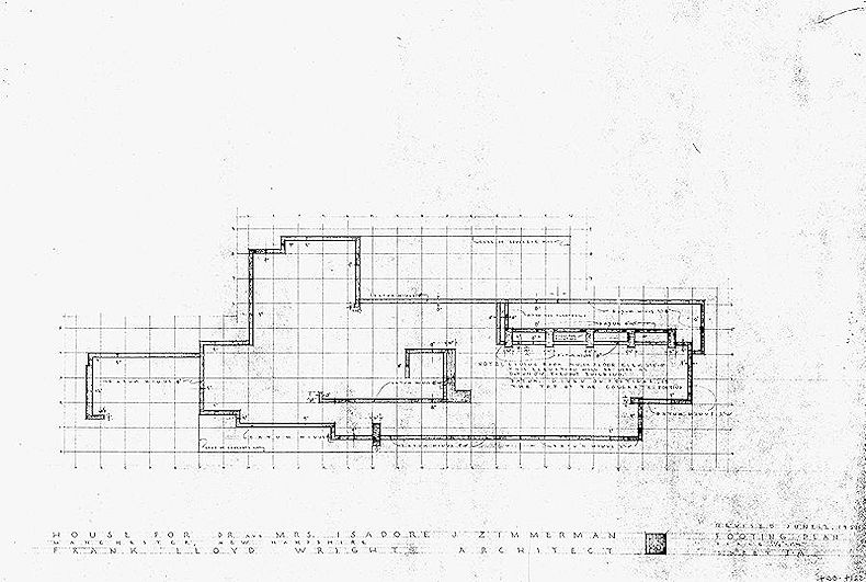
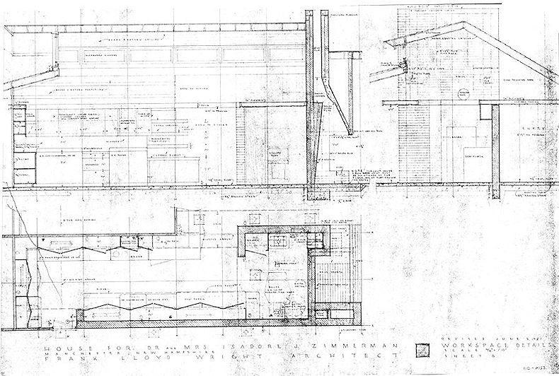
The Building Department Set of Working Drawings Although the entire Zimmerman file is missing from the Frank Lloyd Wright archives, many prints of drawings are still available from the Zimmerman collection at the Currier Gallery of Art. They also have the original set of blue prints that was submitted to the local building department. This is the only documentation of the configuration of the house before the changes that I made at Taliesin before leaving to supervise the house, and are, for that reason, an important set of drawings. For purposed of identification, I will call this set BDSet. The drawings on which I made changes at Taliesin before leaving for New Hampshire can be identified by a “Revised June 2, 1951” lettered above the sheet title in the lower right hand corner. There was no footing plan with the original working drawings, so I drew a new footing plan at Taliesin and numbered it Sheet # “1A” and included the Revision Date June 2, 1951 although it was an entirely new drawing, it still belongs with the drawings with the “Revised June 2, 1951” date. There were to be additional changes to the footing plan that would have June 11, 1951 as the revision date, as do the rest of the new drawings. This was just three days after my arrival so it would appear that I was wasting no time in getting started. I made an entirely new set of working drawings on the job and used the existing sheet title and number followed by an “A” to distinguish these drawings from the original drawings, and they bear a Revision Date of June 11, 1951. Other drawinga that I made on the job are not signed by Mr. Wright, do not have sheet numbers, and are of varying sizes. But back to the front elevation; the pair of perforated block piers defining the entrance has been changed. They didn’t make sense anyway. The idea of the perforated blocks with a glass insert acting as a screen between the house and the street was appropriate. But trying to make piers out of them did not make sense, nor did the use of a pair of piers, which creates an implicit centerline that was going nowhere, while ignoring the approach of the house entrance from the carport. The single brick pier now defined the entrance and bounces you towards the entrance, directing your peregrinations, as good architecture should. There were to be additional alterations to the front elevation but they will come later.
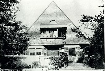
The masonry core defining the workspace and utility functions was dominant as one big rectangle on the preliminary drawings and was visible on all four elevations. It looked plausible in elevation but made no sense in plan. Mrs. Zimmerman had expressed concern about the amount of light in the workspace, and to address that concern Mr. Wright eliminated most of the masonry core walls and added a flat roof over the workspace core with clerestory windows on the garden side of the house. The idea of the masonry core was one of the prime components for the Jacobs #1 concept but inappropriate in this instance. A masonry wall rising above the workspace roof opposite the fireplace survived these changes, shows a flue, apparently for a furnace, and hides the edge of the flat roof of the workspace. The garden countenance changed as well, primarily because of the addition of the bedroom gable roof. The brick piers were still there in the living room, dominating the scene and establishing the character of the house from this vantage point. The bedroom gable was secondary and needed to remain in that way in relationship to the main gable. This ghosts on this sheet show several variations on how to handle the bedroom gable. The problem is whether to follow the example set by the unequally pitched gable of the main roof, or use a more pedantic equally pitched gable. Mr. Wright’s philosophy would opt for following the example set by the main gable, but here he chose an equally pitched gable. Was that the right decision? Who knows? Sometimes following a doctrinaire solution works and sometime it leads to an overly complicated configuration, better avoided. The equally pitched gable roof, by its very nature, implies a center line, and that is exactly what Wright was trying to avoid with the unequally pitched gable roof. Wright’s own 1889 house for himself espouses the typical symmetrical gable roof. It is married to symmetry.
The unequally pitched gable roof just does just the opposite and avoids a center line. The end elevations of the Zimmerman house demonstrate what Wright was doing with the unequally pitched gable roof. There is no realized or implied center line here, and it is obvious that an equally pitched gable roof would not be appropriate in this instance. Wright actually hangs the street side gable off a masonry wall at the ridge which might appear to be non-structural and you might expect it to look that way. But it looks just fine. Structurally it is no different that a flat roof with a cantilever of the same distance. It is just a bent plane.
The new clerestory windows in the workspace are over the workspace-bath wall and extend from the fireplace mass to the masonry wall at the opposite end of the workspace. They read on the garden elevation but not on the street elevation. The clerestory was located over the wall separating the master bathroom and the kitchen in one direction and extended from the fireplace mass to the ridge of the master bedroom, roof returning on that line. In this house, like most of Mr. Wright’s houses, the finish ceiling surface followed the underside of the roof surface. This placed the clerestory return four feet in from the end of the kitchen because that is where the ridgeline was. It made for interesting geometry. One side of the clerestory roof was a continuation of the steeper pitch of the main roof and the return followed the lesser pitch of that roof. Another change was to the fenestration of the master bedroom. The main focus of this elevation was obviously the masonry piers in the living room. The inclined transom bar at the master bedroom tended to attract too much attention to a secondary element that was not part of the main idea and was, consequentially, changed to a level transom bar, which was more appropriate in this circumstance. The fenestration in the living room and its relationship with the masonry piers also needed attention. The masonry pier closest to the fireplace is centered on a half unit line, the next had one face on a unit line, the next also with one face on a unit line but on the opposite hand, the next is back on the half unit line and the last again has one face on the unit line like number two. The locations are following the criteria of the unit system. The spacing is in scale with the involved space and produces an opening of five feet four inches between piers. When you hang a four foot window module between the piers you are left with an eight inch sidelight on each side. This is just fine. It is interesting, and although the window units don’t conform to the unit system, it does add interest to the geometry much like syncopation does in music. It is the exception that proves the rule, and Wright’s work is replete with left over spaces, all as a result of the unit system. Wright was not one to arbitrarily follow the rules anyway. The next problem was the vertical mullions. The piers were all the visual and structural support the fenestration needed and the mullions were redundant. So out with the mullions. That portion of the mullion defining the sash must necessarily stay in place. But the pair of sash became one single sash. This was not an ordinary circumstance for a window and an ordinary solution was not appropriate. The final solution created a single horizontal element of the fenestration that had a reverse relationship with the vertical piers and it all worked wonderfully. The horizontal nature of the fenestration tended to emphasize the idea of the dominance of the piers in the scheme as a whole. These were not all the mandated changes but time had rum out, and the drawings were printed and sent off to the client. I would follow soon after. Arriving on site, my work with the drawings continued. The last major revision was to the carport area. The first part of the problem was the storage area. It followed the typical Usonian example of a two-foot deep storage area at the outside end of the carport. That was fine for the flat roofed Usonian with 6’-9” ceiling. Here we had had a twelve-foot high gabled ceiling and the two-foot storage unit was inappropriate. It would look skinny and totally out of scale considering the mass of the house proper. This solution was an example of carrying forward an idea that worked in the original instance but not here, and had been placed into the design by rote. The storage area would become an eight-foot square room, giving the carport roof the visual support it needed and also bringing the elevation into balance. Wright said that his buildings were not always symmetrical but they usually had balance. Initially, too, the rear wall of the carport bore a repetition of the perforated concrete blocks used to screen the house from the street. This was another inappropriate use of the blocks and not part of the idea of their original use. They had to go and they did. That allowed the wall to be lowered to the same height as the windowsill of the two bedrooms and simplified the elevations. Wright loved taking care of the terminals and he did it with assurance in this instance. “Terminal masses are important as to form. Nature will show you this in her own fabrications. "Take good care of the terminals and the rest will take care of itself." (Frank Lloyd Wright, American Architecture, p. 61). The two brick masses at the terminals of the building embrace the entire house, give visual support to the roof, and present a simple, but not plain, countenance to the street. A stair was added at the far end of the carport for access to the garden side of the house. The brick wall separating the workspace from the entrance hall worked to visually unite the two brick and perforated block walls that are separated by the entrance. While it is an interior wall it is still visible through the void that in the entrance fenestration and fulfills the uniting function. The other major change was to the roofing material. The local building codes required a noninflammable roofing material so the specified wood shingles were changes to clay tile shingles. It was an expensive change but added immeasurably to the character of the house. It also required a redesign of the supporting member of the roof. The roof ridge in the garden room occurs on the face of both fireplace and the brick mass at the far end of the room where the street side of the gable is simply hung from the ridge with no natural support. A steel beam follows the pitch of the garden side of the roof with a welded joint at the ridge and then on down to the eave on the street side of the roof. A similar condition occurs at the carport roof where the ridge is again on the street face of the storage room. There are also steel beams at the ridge and at both eaves at the carport.
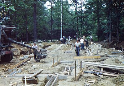
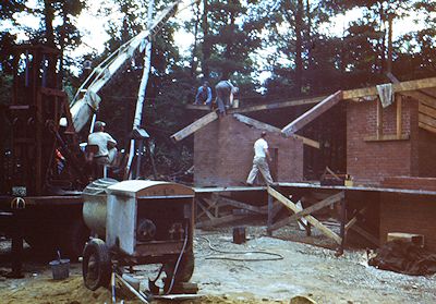
construction As mentioned earlier, the excavation for the footings had already begun when I arrived at the construction site. The rock outcropping around which the house had been oriented was in the way of the backhoe and had been pushed aside. It wasn’t that big a problem. We just repositioned it at the appropriate time. The footings were Wright’s typical crushed stone foundation and I guess they work. The house is now some years old and there are no sign of settlement. In this case we added an eight-inch square grade beam to receive the masonry walls and the loads applied directly to the slab at the building line. The exception to the rule was the outside edge of the exterior slab at the dining area, which later became a problem. The first actual building problem occurred early in the game. The brick masonry was specified as the typical Wright manner with raked horizontal joints and flush vertical joints with mortar the same color as the brick. This was New England with stubborn New England workmen. I struggled with the masons for days trying to get the vertical joints properly filled. But the masons could not, or more likely would not, master the technique. This was a cost-plus job and time and money were being wasted. So, I relented and abandoned the filled vertical joints. It is not a major problem but I regret not being more forceful in demanding adherence to the specifications. It would have been a better house with the filled vertical joints. The perforated blocks and wall copings were cast on site and in the final scheme of things turned out just fine. I didn’t like the raw look when they came out of the forms so we toweled on a skim coat of colored cement which worked just fine but cost money. The first problem with the building contractor began with the billing in connection with the masonry. The client was being billed for all scaffolding brought onto the site and then credited when the materials were returned to the warehouse. The trouble was that there were always shortages of returned items that the owner ended up paying for. My position was that these were items of service and were part of the contractor’s overhead. It was really just a scam to fleece the client. When the slab was poured the real problem surfaced. Concrete is an imperfect material at best and to treat it as a finished material is fraught with problems. In this case the pour was well done but one unit line ended up on the wrong side of a pier in the garden room, a major problem. The contractor agreed to remedy the problem by shipping off one inch of the surface and re-pour it. Mrs. Zimmerman was such a perfectionist that more of the slab was replaced than was appropriate. When the time came to pay for it was when the real problem surfaced. By this time the house was enclosed, as we say, and it was decided that I would assume the contractor’s position and would finish the house. The other problem was an adequate supply of cypress. It was a problem in the beginning and continued to be a problem to the end of the job. The rest of the construction process was a fascinating experience but one that would not bear repetition. I returned to Taliesin after my year sojourn in the east. Mr. Wright stopped me one day in Arizona under the pergola outside the drafting room and said, out of the blue, “I know it not easy being back here after being out there in touch with the glory of the thing.” I was flabbergasted, not only that he had taken notice of my state of mind but that he has made a point conveying that thought to me. Wright had many personas but that is the Frank Lloyd Wright that I knew. See also: Archival documentation related to this commission can be found in the Geiger collection, Architectural Records, Residence for Dr. and Mrs. Isadore Zimmerman, and The Zimmerman House Timeline. Note 1: There is a further comment about the relationship between the Dabney and Zimmerman houses in another draft of this manuscript: "The Zimmerman scheme was an adaptation of the Dabney house, which was a slightly schizophrenic concept with a combination of unequally pitched gable roofs and a flat roof with a lapped board fascia, the two being joined by a row of clerestory windows. It was an unhappy combination of forms that did not conform to Wright’s own dictum of organic; “In organic buildings nothing is complete in itself, but is only complete as the part is merged into the larger expression of the whole.” Future, p. 66). Had the flat roof been another gable and the clerestory retained, it would have been a very interesting house. Schizophrenia is difficult to cure, however, and Dabney didn’t make it. With a little more therapy it might have survived. The relationship of the dining area to the bedroom gallery would have been interesting and survived in the first Zimmerman design." Return to text |