|
To a greater or lesser
degree depending on the building, why is a Wright building beautiful? That beauty is rooted
in the spatial quality of the building, and the space is a
function of the geometry of the planes that determine the basic
character of the structure. Strong geometry appears first in the
floor plans of the earliest work but spatial quality appears,
along with geometry, a bit later in the Playroom of 1893 and the
Oak Park Studio of 1895, personal spaces for Wright. I make a
distinction between spaces that Wright created for himself,
‘personal spaces’, and those he created for clients. He lavished
his greatest talent on his own personal environments. He lived
in these spaces and molded them to his will until they required
no further refinement. I have discussed these particular spaces
earlier.
I admit that I came to my basic conclusions quite
inadvertently. While reading an essay about the influence of
Froebel on the manner in which Wright used geometry, in this
case with the Ross cottage, I found myself thinking, “This is
sheer nonsense. Wright simply did not think that way.” This
raised two obvious questions. The first is, if he didn’t think
“that” way, how did he think, and secondly, how did I know how
Wright thought? I had been exposed to Wright’s work for some
fifty years at this point and obviously drawn some
conclusions as to how he proceeded to solve architectural
problems. That didn’t mean I approached the problem solving
process by intellectual examination, but
nevertheless I had
concluded, at least in very broad terms, how he approached the
architectural design problem. The next step was to examine how
he thought, or did not think, about the Ross cottage.
The earliest published drawings of the Ross cottage were
drawn especially for Frank Lloyd Wright's
Ausgefurte Bauten; the Hitchcock
drawings are derivatives of these drawings. They are all right
for their intended purpose but are not adequate for serious
examination. Neither the preliminary nor working drawings have
ever been published, so a visit to the Getty Research Library
was in order to examine images of the original drawings. Before I get to
the Ross cottage, however, there are precursors to be
considered bridging the gap between Wright’s 1889 house for
himself and the 1902 Ross Cottage. After all, this is a period
of 13 years. A sea change had taken place in Wright’s design
vocabulary. The Ross cottage of 1902 is not only fascinating for
its geometry, but is also prototypical of almost all the
relevant forms common to Wright's residential work from 1902 to
the time of his death in 1959.
THE ROSS COTTAGE
PRECURSORS
By 1902, Wright was a major force in the field of
architecture with several masterpieces to his credit, including
the 1893 playroom added to his 1889 home, the 1895 Studio, the
1896 Romeo and Juliet windmill, the 1900 Bradley and Hickock
houses, and in 1902 the Heurtley and Willits houses, the
Hillside Home School buildings, and the Ross cottage.
The Ross and other concurrent cottages are of particular
importance for their simplicity and originality of concept. They
tend to be simple direct solutions to a problem. By 1900, he
reached a new plateau of maturity with the Pitkin cottage. Like
Wright’s own 1889 house, the Pitkin project is no masterpiece,
but the design is important for the ideas that it represents.
The most obvious feature of the scheme is the broad rectangular
stylobate that serves as a base for the entire structure. The
device is similar to the verandas in Wright’s 1889 house, but
here is used much more decisively. The main body of the house
is a simple rectangle that occupies the center portion of the
stylobate and is congruent with it at the back wall. There is an
8’-0” wide cross rectangle defined by two service areas
at the outside corners of the stylobate at the back. These
alignments create a cross gable at the first floor whose ridge
is in-line with the back wall of the second floor. The effect
produces a consciously designed relationship that approaches the
cruciform: what this cottage is all about. This
device is obvious on the elevations, as well as on the floor
plan, if you look. The broad chimney mass, which
becomes dominant in future
work, appears here for the first time and requires a walk
through on the second floor, but does emerge as an exterior
design element. Also, the first real, but incomplete, unit
system makes an appearance. The Swiss Chalet
look is out of place in the context of the ideas demonstrated in
the concept of the job, which is clearly Wright’s. That look is
particularly offensive on the South Elevation. The East
Elevation best reveals Wright had in mind.
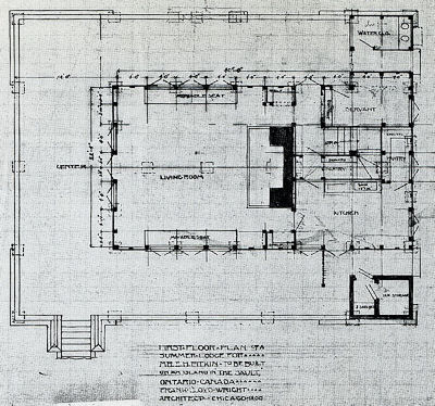 |
| Figure 1. Pitkin Cottage First Floor
Plan. Frank Lloyd Wright Archives, Drawing #0005.001 © Frank Lloyd Wright Foundation. Used by permission. |
| |
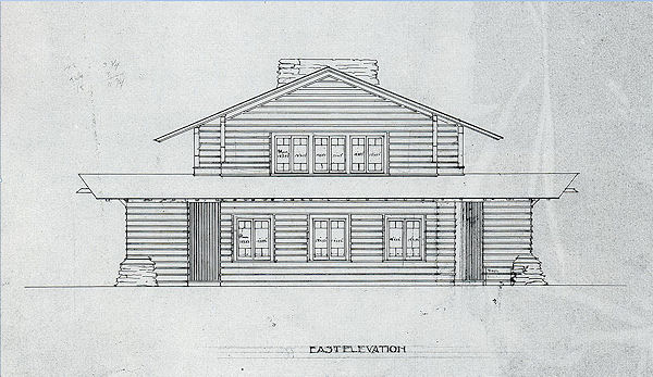 |
Figure 2. Pitkin Cottage East Elevation. Frank Lloyd
Wright Archives, Drawing 0005.009
© Frank Lloyd Wright Foundation. Used by permission. |
| |
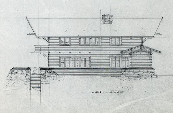 |
Figure 3. Pitkin Cottage South Elevation. Frank Lloyd
Wright Archives, Drawing 0005.007
© Frank Lloyd Wright Foundation. Used by permission. |
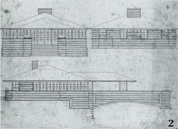
The George and Walter Gertscottages (Figures
4 and 5, and Figures 6 and 7, respectively) are
important for their clarity and elegance of concept. There is
nothing unaccounted for in these designs. Each is contained
under one big roof, a device that will become a hallmark of
Wright’s future work. The unit system is fully developed here,
except that he throws an occasional odd unit in each case to
accommodate a smaller dimension for the “pier” in the George
Gerts cottage. The pier makes a decisive appearance here for the
first time. The pier is essentially a masonry form and this
presence in a board and batten structure is somewhat
problematic, but the arrangement works architecturally to
provide visual structural support where needed.
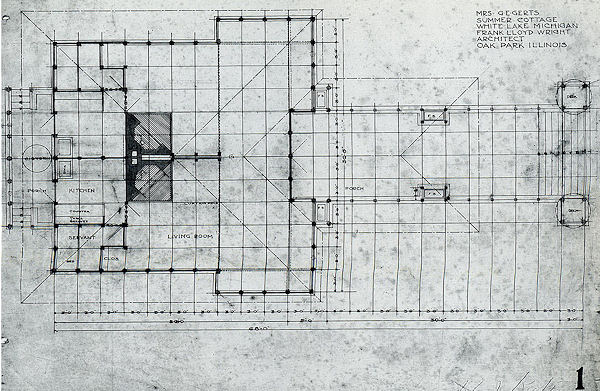 |
Figure 4. George Gerts Cottage Floor Plan. Frank
Lloyd Wright Archives, Drawing #0202.001.
© Frank Lloyd Wright Foundation. Used by permission. |
| |
 |
| Figure 5. George Gerts Cottage Elevations, Frank
Lloyd Wright Archives, Drawing #0202.002. © Frank Lloyd Wright Foundation. Used by permission. |
| |
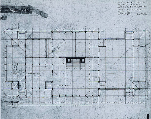 |
Figure 6. Walter Gerts Cottage Floor Plan. Frank
Lloyd Wright Archives, Drawing #0203.001.
© Frank Lloyd Wright Foundation. Used by permission. |
| |
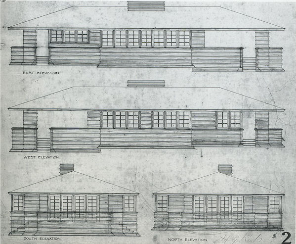 |
Figure 7. Walter Gerts Cottage Elevations. Frank
Lloyd Wright Archives, Drawing #0203.001
© Frank Lloyd Wright Foundation. Used by permission. |
THE ROSS COTTAGE
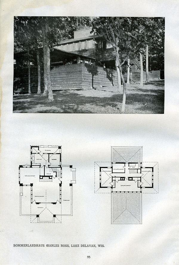 |
| Figure 8. Floor Plans and Photograph. Frank
Lloyd Wright, Ausgefuhrte Bauten |
The Ross cottage is the last of the structures that has a
pronounced stylobate, which here is the primary element of the
design. This work is simply amazing for clarity of
concept. Wright contemplates an entirely new architectural
grammar that he senses only in big overall terms. Any new
concept has to start this way. An idea must be worked
until the light bulb goes off and understanding occurs. We have
all experienced this; possibly in algebra class, or maybe
English Literature. Wright was not fully aware of what he
had done in this case, and that doesn’t really matter; the
essential grammar was evident.
The original drawings are in a somewhat distressed state, but
I would like to use them here anyway since they have never
before been published and they do provide a lot of information.
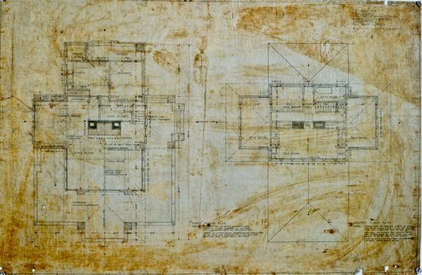 |
Figure 9. First and Second Floor Plans Frank
Lloyd Wright Archives, Drawing #0206.002.
© Frank Lloyd Wright Foundation. Used by permission. |
| |
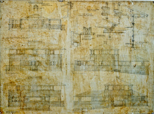 |
Figure 10. Elevations and Details. Frank Lloyd
Wright Archives, Drawing #0206.001.
© Frank Lloyd Wright Foundation. Used by permission. |
There are also two additional elevation sheets
that were obviously drawn much later:
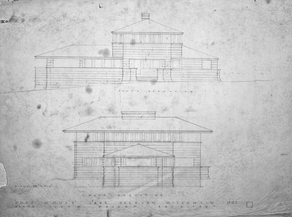 |
| Figure 11. Elevations. Frank Lloyd Wright Archives,
Drawing #0206.003. © Frank Lloyd Wright Foundation. Used by permission.
|
| |
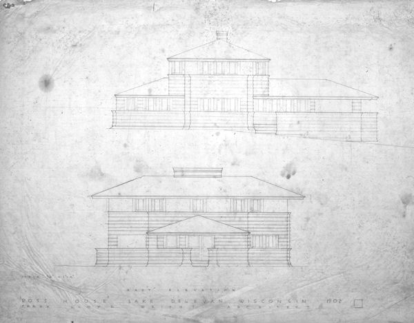 |
| Figure 12. Elevations. Frank Lloyd Wright
Archives, Drawing #0206.004. © Frank Lloyd Wright Foundation. Used by permission. |
The house consists of three basic elements: the
stylobate or base on which the house rests, the lower hip roof,
and the upper hip roof turned 90 degrees to the lower. This
disposition of two equal width hip roof lines at a right angle
to each other is the hallmark of Wright's work for years
to come and emerges as a major factor in their beauty. The
geometry of the plan is as exact as any classical temple. The base
is thirteen units square and defined by the six major
piers. The lower hip roof, seven units wide and nineteen units
deep, centers on the stylobate, overhanging by one unit on
the front and extending beyond the stylobate five units on the
back. The upper hip roof is also seven units wide and overhangs
the stylobate on three sides by one unit, so that the
diagonals of the hips coincide with the diagonals of the square
stylobate base. The seven, one quarter unit square, visually
supporting piers have their diagonals on the diagonal of a hip.
The smaller columns determining the exterior closure line of the
living room are in line with the two larger columns at the front
and have one corner on the diagonal of the base. The chimney has
one face on the ridge line of the upper roof and is centered on
the ridge line of the lower roof. All this is very
geometrically regular but not dull or static
(Figure 13).
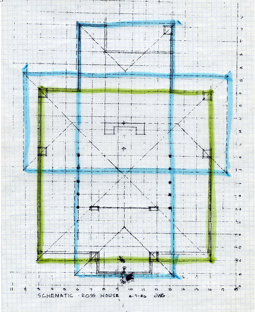 |
| Figure 13. Ross House Schematic Plan. John W. Geiger |
I have chosen to use this plan (drawn August
9, 1986) because it is dated and because it is enhanced by the
imprint of a beloved feline friend. I used green to outline
the stylobate because it is the closest to earth and blue for
the two roof outlines because they are closest to the sky. I
find the geometry demonstrated here to be absolutely fascinating
for the implications in his future work. As you have probably
noticed, I have drawn the stylobate as defined by the six square
piers because that is what was uppermost in Wright’s mind. The
front railing varies from the basic scheme and was a
mistake. Wright trys to do two different things here and
the combination doesn’t work.
The stylobate and the lower roof and upper roofs should
be considered as parallel horizontal planes. Separated by a
story height, they float freely in space, with the additional
plane of the earth being considered as the primary plane to
which the other planes are related. If you come in one unit line
from the roof perimeter and drop a vertical plane, you have the
space available for use as enclosed space. This form can
be considered for a one or two story space as required. Where more
space is needed, either for practical of aesthetic requirements,
the enclosing vertical plane can be moved out to the roof edge,
but no further. The plane can also be moved inward from
the one unit line for similar reasons, as in the living room.
The position of the two roofs can also be reversed,
as in
the two story living room of the Isabel Roberts house.
A space is generated between the plane of the first floor
roof and the stylobate. The stylobate continues outside the
confines of the lower roof to form a relationship with
the next available plane, which is the sky, wherever that happens
to be. The second floor roof not only creates a relationship
with the two constructed planes below, but where overhanging the
stylobate conversely establishes a relationship with the next
available plane below, which is the earth. Wright
renders a relationship with both earth and sky.
However, there is one big problem the way in which Wright
develops this scheme: the relationship of the front line of the
stylobate parapet to the roof above. He moves the parapet off
the unit line to the inside face of the wood pier and introduces
a projecting stylobate between these piers. This device
makes the piers appear to be free standing. The other
four piers defining the stylobate are in line with the parapet.
The front parapet should also be in line with the front
piers and on the unit line. He is trying to do two
different things with this front parapet where he should be
doing only one. He has already a schematic relationship
between the stylobate and the roof plane above
through simply
overhanging the stylobate by one unit. What he is trying to do
with the center projection is the reverse of what he has already
achieved; namely to project the stylobate with its attendant parapet
one unit beyond the roof line. He does this in a mature way with
the Robie house west terrace in 1908. This is 1902,
though, and
Wright is struggling to invent an entirely new way of looking at
architecture as a series of related planes. He pretty much does
that schematically with the Ross cottage, but a full realization
of what he had done had not yet entered into his conscious
thinking. That is understandable, considering the scope of his
undertaking.
With Robie he includes the balcony off the living and dining
rooms, and the staircase from the terrace down to the first
floor is in the equation. The two configurations of the
Ross schematic and the Robie west terrace are really the same
thing; one being the reverse of the other.
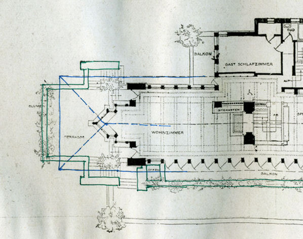 |
| Figure 14. Robie House Main Floor Plan, with colored
overlay by John Geiger. Sourced from Ausgefuhrte Bauten
Frank Lloyd Wright, p. 113. |
I am calling this simple relationship the Wright Paradigm, or
the WParadigm for short. This basic relationship will occurs
again and again in different guises in all of the best work for
the rest of his career. I see the relationship as basically
between two, or more, horizontal planes, but the vertical plane
of the balcony or terrace parapet also plays a secondary role as
a vertical plane forming a horizontal to vertical relationship
as well.
I also think that once Wright became aware of the WParadigm,
he saw it as a very simple key to produce quality in his work
and continued to keep the secret of how he worked from everyone,
including the staff. Maybe he didn't really see this approach
as a secret, but simply as his way of working. Possibly it just
never occurred to him that he might share the technique with
anyone else. He lived in a world of his own creation that was
not well populated with friends or enemies; or a wife and
children, for that matter. His one big need in life was to be
architecturally creative, and the second was for female
companionship.
The stylobate of the Ross cottage was to make its last
appearance for years to come, but the cruciform roof pattern is
the configuration that will have the greatest impact on the work
for the next five or six years. The form dominates all the best
work. The WParadigm will come later. The Walser, Barton and
deRhodes houses of 1903, 1903, and 1906, respectively, are
direct developments of the Ross cottage. The 1902 Willits house
and the 1904 Martin residence are both extremely sophisticated
examples of the cruciform roof pattern. Like Wright’s 1889 for
himself, the main roof dominates the composition. In both
of these houses Wright takes great care to keep all the major
architectural features of the house under outline of the
roof. There is no indication of the WParadigm. In the Willits
house, Wright extends the living room as a terrace at the front
of the house but takes care that the second floor roof has a
tight eave with the front elevation. There is no overhang of the
terrace by the roof, thus avoiding the WParadigm. Still, the
roof pattern is the dominant design consideration. The floor
plan had to fit the roof plan.
The roof plans of the Willits and
Martin houses that follow
clearly demonstrates the existence, and the importance of, the
roof as a geometric pattern, and the subservience of the floor
plan to that geometry.
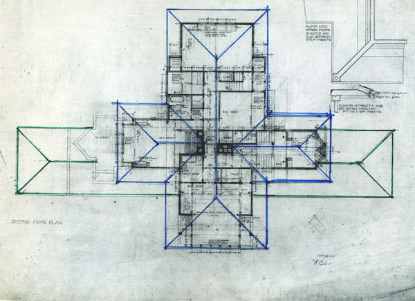 |
| Figure 15. Willits house roof plan, with colored
overlay by John Geiger. Frank Lloyd Wright Archives,
Drawing #0208.004. © Frank Lloyd Wright Foundation. Used by permission. |
| |
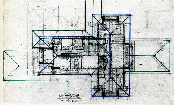 |
|
Figure 16. Martin house roof plan, with colored overlay by
John Geiger. Frank Lloyd Wright Archives, Drawing
#0405.005. © Frank Lloyd Wright Foundation. Used by permission.. |
The WParadigm of the Robie house might not seem like a
sea change from the Willits and Martin houses, but it is, and as
such marks the end of the Oak Park Grammar as well as Wright’s
Oak Park life. Here is the beginning of the establishment of a
relationship between the floor plane and the roof plane that
would pervade Wright’s work for the rest of his life. The Oak
Park grammar had run full course and change was in the offing.
A GIANT LEAP FORWARD
To start the giant leap forward, let us draw an
imaginary line in the sand. Take the Ross cottage schematic and
project the corners of the stylobate and the first floor roof
over the line in the sand. Then rechristen that line in the sand
a waterfall.
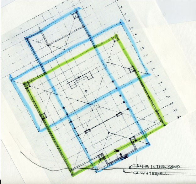 |
| Figure 17. The Ross schematic, revised. John
W. Geiger |
And what do you have?
You have Fallingwater.
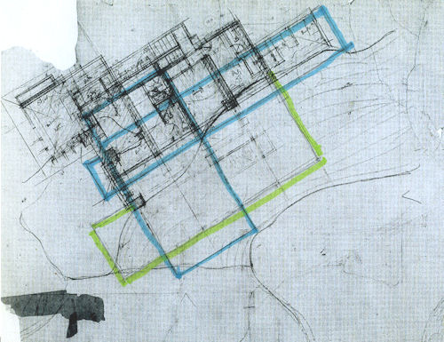 |
| Figure 18. Fallingwater, Original Sketch by Wright,
with color overlay by John Geiger. Frank Lloyd Wright
Archives, Drawing #3509.166.
© Frank Lloyd Wright Foundation. Used by permission. |
| |
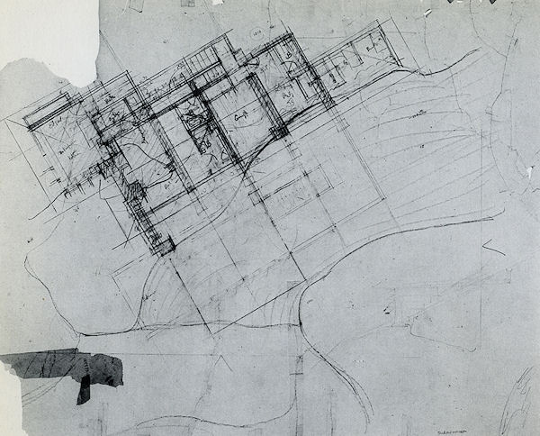 |
| Figure 19. Fallingwater, Original Sketch by Wright.
Frank Lloyd Wright Archives, Drawing #3602.166. © Frank Lloyd Wright Foundation. Used by permission. |
I have repeated the drawing without my intrusion
so that you can see that I only enhanced lines already
drawn by Wright.
What makes Fallingwater “work” is the overlap of the two
constructed planes of the first and second floors with the two
natural planes of the top and the bottom of the waterfall; hence
the engagement of the fall of the water from one plane to the
other; or Fallingwater.
The rest is history.
|
|